Unboxing
What’s Inside
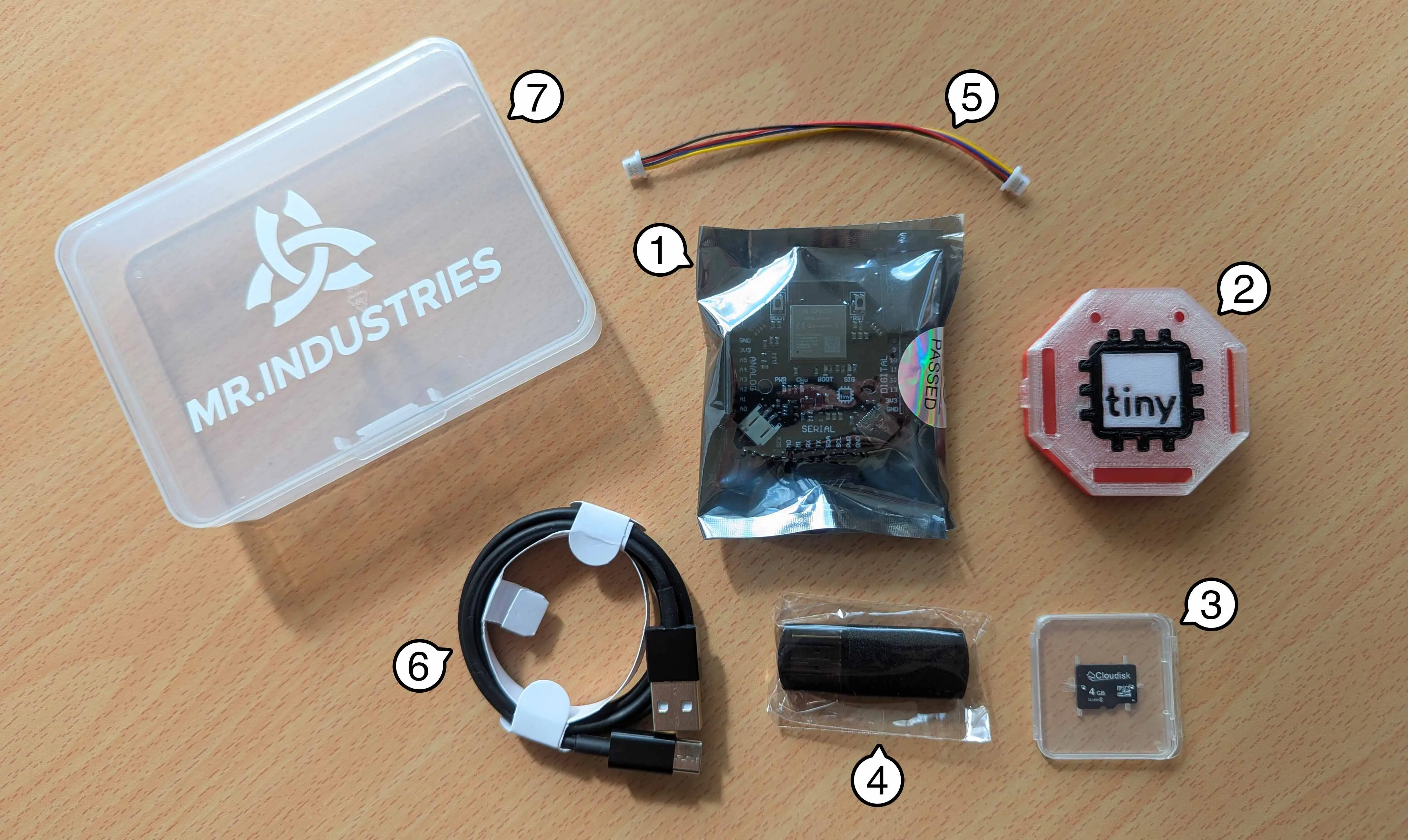
Section titled “What’s Inside”Inside your tinyCore V2 Kit, you should find several things to help you get started:
| Label | Item | Quantity |
|---|---|---|
| 1 | tinyCore V2.0 Development Board | 1 |
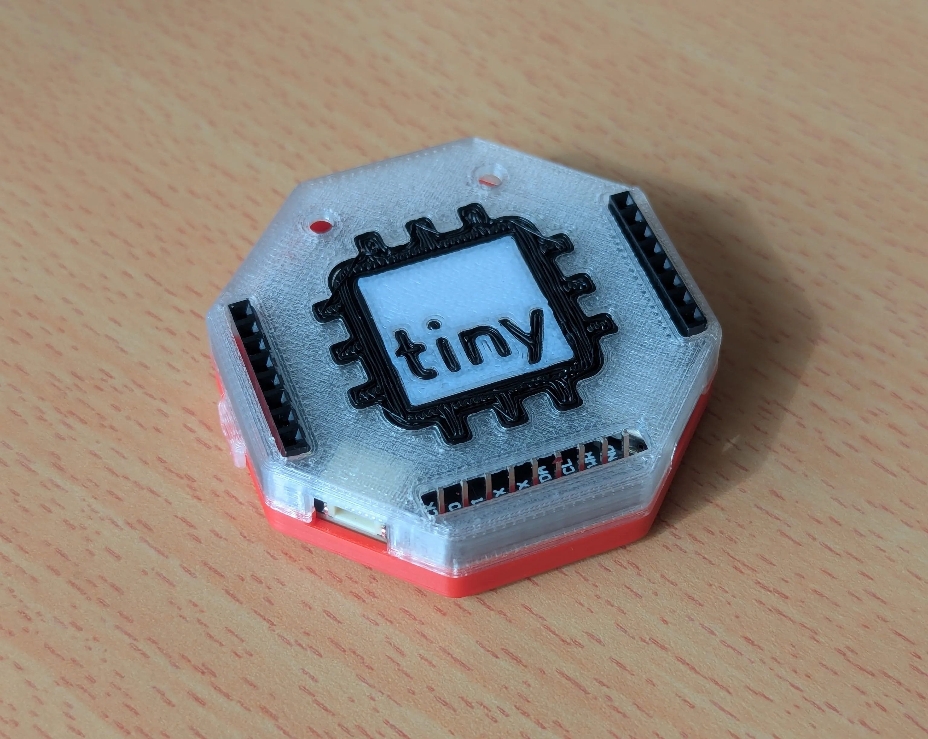
| 2 | 3D-Printed Multi-color Snap Enclosure | 1 |
| NP | M3 Machine Screws (for Enclosure, don’t lose these!) | 2 |
| 3 | Micro SD Card (4GB) | 1 |
| 4 | USB Micro SD Card Reader | 1 |
| 5 | STEMMA/QWIIC Cable Connector (100cm) | 1 |
| 6 | USB-C Programming Cable (1m) | 1 |
| 7 | Plastic Project Box (11.5x8.5x2.8cm) | 1 |
| NP | Secret sweet treat! 🤫 | 1 |
NP = Not Pictured
Preparing the Headers (Optional)
Section titled “Preparing the Headers (Optional)”Here’s your first big challenge: Soldering the headers!
You must be careful, since they are “key-ed”1 by number of pins. This means they can only be soldered correctly in one configuration.
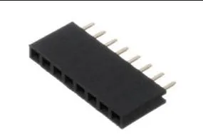
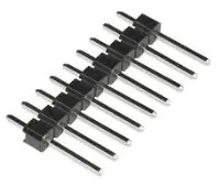
We have three headers to solder, two female (8 pins), and one male (9-pins)
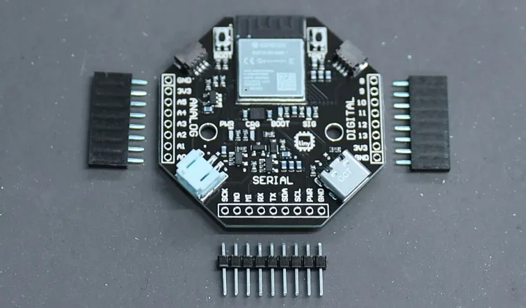
The female headers look like this, and are for the left and right (Digital and Analog) pins.
The male headers look like this and are for the bottom (Serial) pins:
Put the female headers in while the is PCB face up, then flip over the board and solder.
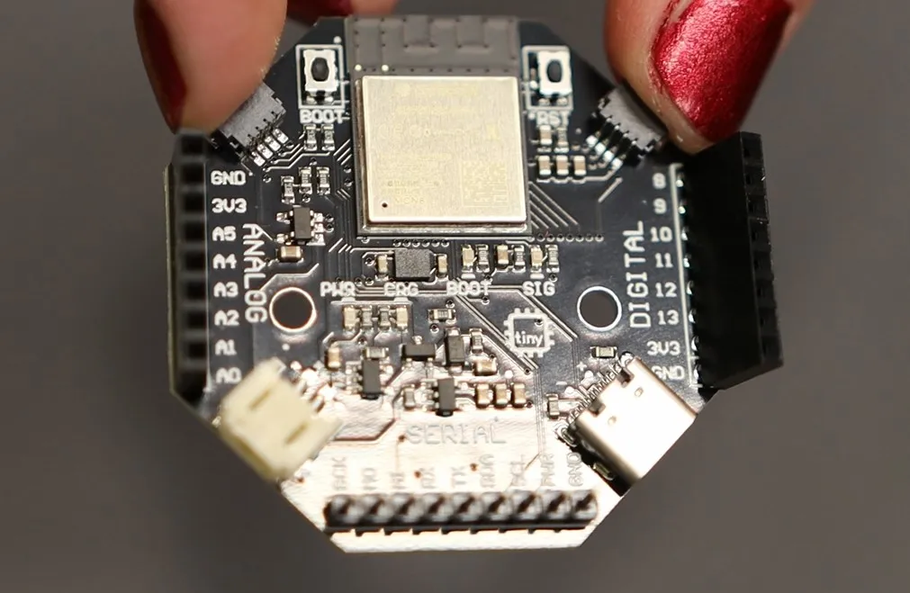
After soldering in the female headers, you can place in the male header pins, and solder these too. Make sure that you put the short end of the male headers through the board!
Assembling the Enclosure
Section titled “Assembling the Enclosure”Once the headers are soldered, we can put the PCB in the enclosure!
-
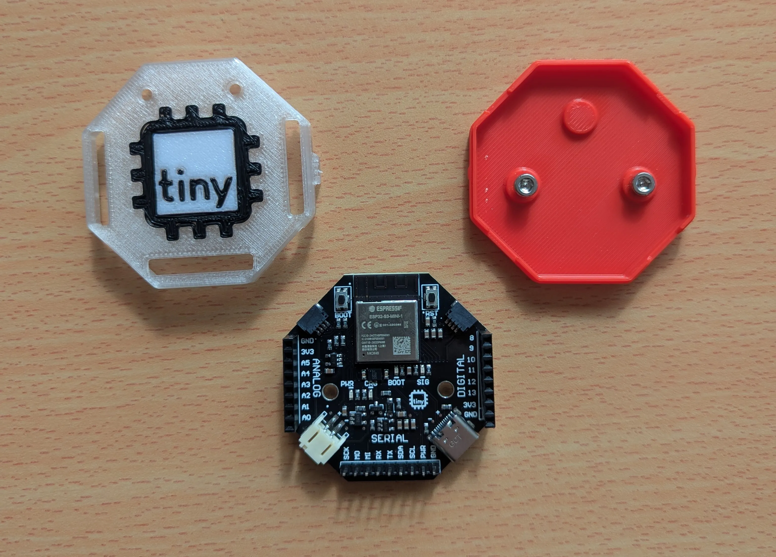
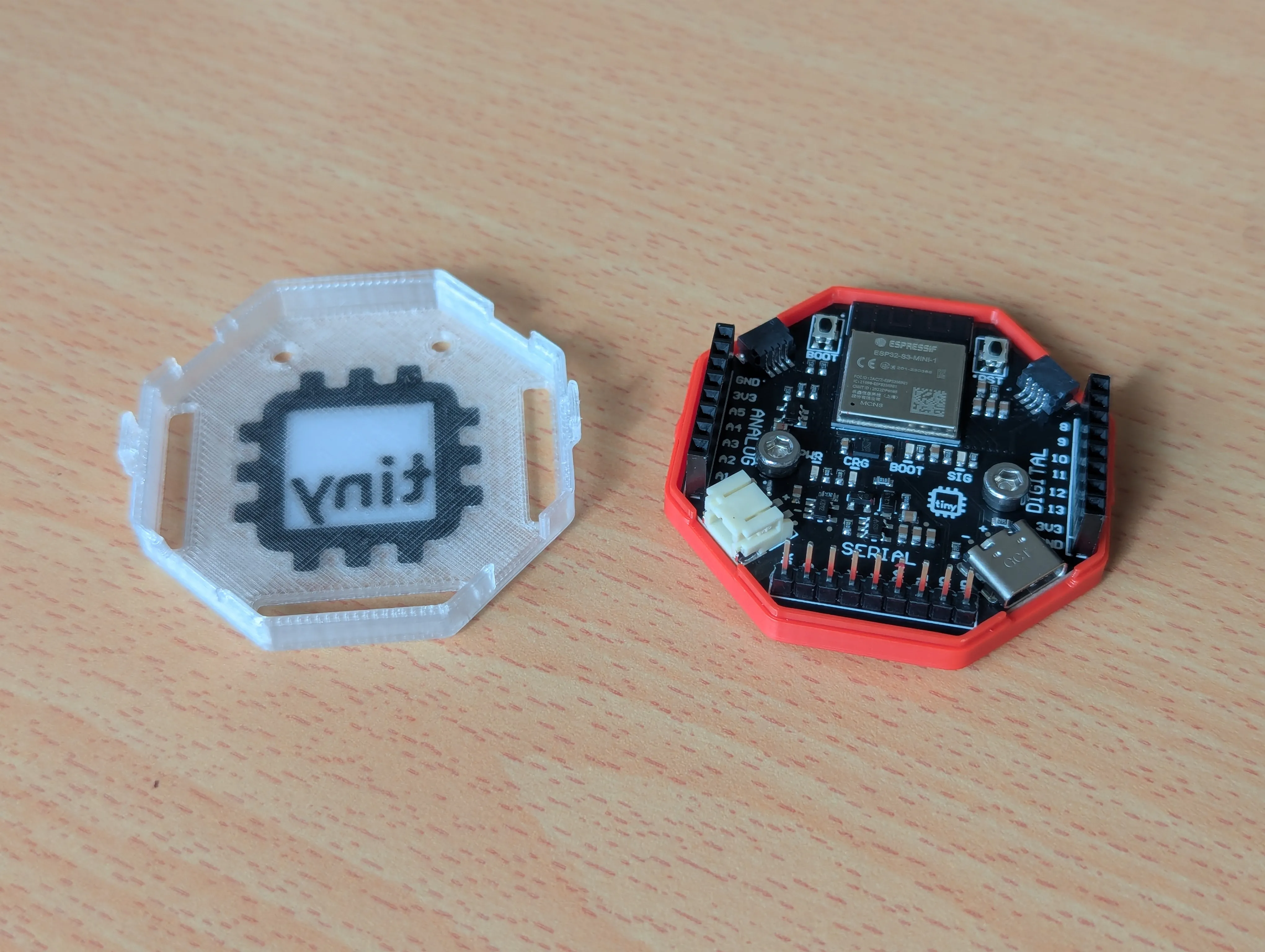
First, gently open up the clamshell2 body of the enclosure. Unclip the hinges and open up the shell.
-
Remove the screws, and place the PCB so that the screw holes line up with the holes in the enclosure. The solid plastic dot goes towards the top!
-
Then replace and tighten the M3 Screws provided in your kit.
-
Return the cover to it’s original position, making sure that the headers align with the holes in the top.